Square wave to sine wave circuit with Arduinoīy the end of my first week my attention had moved back onto the input – I had now abandoned the amplifier altogether. Over the course of the following days I tried various new amplifiers using both the original PNP BC557B transistor as well as the BC457 and BC457B NPN transistors but all to no avail. This proved to be the beginning of a task that lasted well over a week, namely, producing a working transistor amplifier. This still wasn’t producing an audible noise and after running an oscilloscope over the amplifier I discovered that the amplifier wasn’t amplifying at all. This time about two or three feet in length. However, this wasn’t giving any form of output either – I assumed because the low frequency (160Hz) was being tuned out by the tuning circuit and we soon returned to the antenna. A few hours later I was using an Arduino generated sine wave as my input. Meanwhile, Lewis – who was managing and helping me – was creating a circuit on an Arduino which would produce a rough sine wave. Preferring a more reliable input I set about researching possible alternative inputs such as circuits that produced a rough sine wave. However, this antenna was only around a foot in length, (an inadequately short length as I later discovered) and I wasn’t getting any form of noise output from the earpiece.
#Building a transistor radio generator
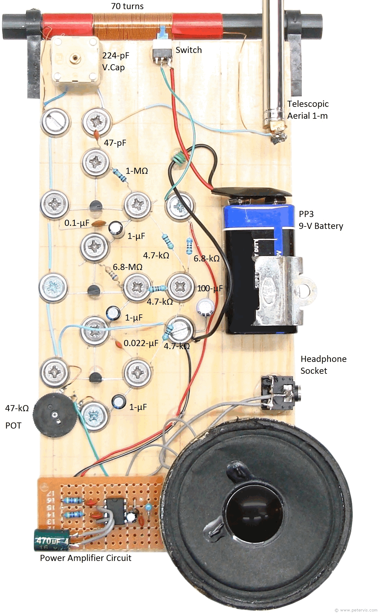
However, without an input from a signal generator or an antenna I couldn’t test this circuit.Īt this point I had an antenna that provided an input into the circuit. By the end of my first day I had built stages one to three of the book (tuning circuit to biased transistor amplifier). To complete this stage I had to solder some short wires to the necessary legs of the variable capacitor and coil so that they could be connected to the breadboard. To match this up with the new value of variable capacitor, I used an equation that I got from one of my teachers at college :- original number of turns(original capacitance/new capacitance) = 50(500×10 -12/266×10 -12). The main part of this task was to create a ferrite coil inductor. The first thing I had to do when I started my two weeks was to create the basic tuning circuit. Finally, due to the different characteristics of some of the replacement components, other components such as resistors and capacitors had to be experimented with to find the ideal values.

Some of these components were the same as the ones in the book, such as the crystal earpiece, whereas modern replacements had to be sourced for others, such as the 500pF variable capacitor. The reason for completing the task before I began was so that the necessary parts and components could be ordered in time for me to begin working on the circuits as soon as I started. So much so that I had a components list completed by late November 2018. This was a task that I began months before my two weeks started in January 2019. The first task that needed completing was the act of sourcing new components and creating a component list. Nevertheless, the project was challenging and definitely showed gaps in my knowledge. Fortunately, this is an area of my knowledge that has been improved and widened over the last two years. However, it did require a lot in the way of electronics. This time the task involved no programming/coding, so my lack of knowledge in that department wasn’t an issue. Unfortunately, due to unforeseen complications, I was unable to get this far in just two weeks.

I had to source replacement components – a task that began long before the start of my two week placement – and I was also tasked with writing up some corrections for the book so that it can be used in modern times. Problems arose in that this book was published decades ago and many of the components are obsolete, ergo, the task involved more than just creating a crystal radio set. This time I was tasked with creating a crystal radio set based on the descriptions and schematics in ‘ Making a Transistor Radio’.

For this I had to complete a second fortnight of work experience, hence the reason for my second visit. Since then, I have gone away and started a BTEC at Brockenhurst College. You may remember if you read the blog, that on my previous visit here I was tasked with creating a timer for the clock pendulum at St. So, I’m Mitchell Granger and this winter I had the pleasure of completing my second fortnight of work experience at Embecosm.


 0 kommentar(er)
